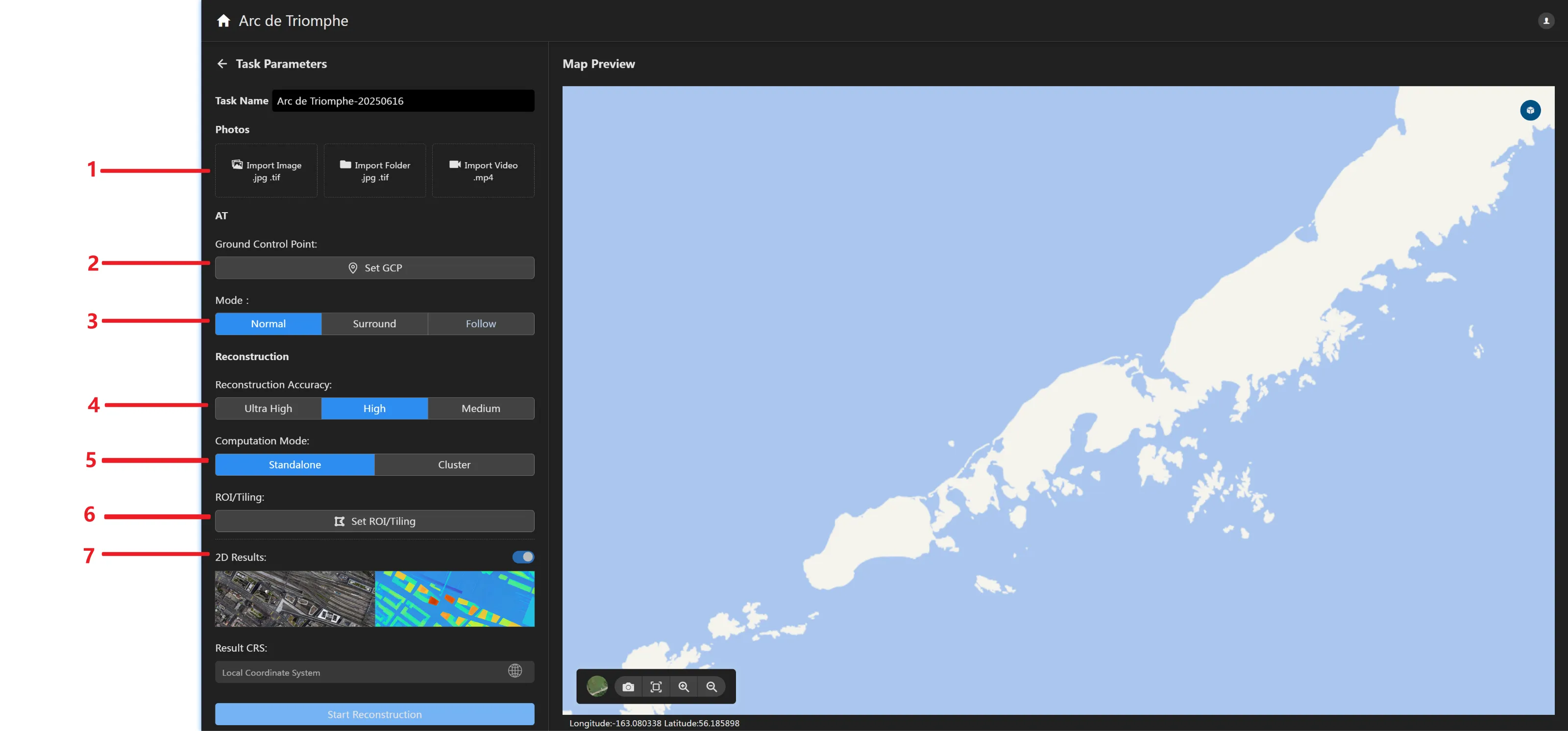
Import Data Panel
Input images (JPG/TIF) and POS data. Supports image input by image or by folder. Supports automatic POS reading from images and manual POS import from external files. Supports camera merging, deletion, and parameter editing.
Input video (MP4/WMV/AVI/MOV/MPG) data. Reconstruct by extracting frames from the video. Supports setting start and end times and time intervals. Supports reading video resolution and predicting the number of photos after frame extraction.
Set Ground Control Points Button
Click the button to enter the ground control points setting page. You can set ground control points and perform point marking to improve aerial triangulation accuracy. For details, please refer to Set Ground Control Points.
Set Aerial Triangulation Mode
Click to select the aerial triangulation mode, including normal mode, surround mode, and close-range mode. Supports selecting the corresponding aerial triangulation mode based on the image data acquisition method. Normal mode corresponds to most acquisition methods such as UAV orthophoto and oblique. Surround mode corresponds to surround target acquisition. Close-range mode corresponds to close-range target acquisition.
Reconstruction Accuracy Setting Panel
Click to select reconstruction accuracy: High (best effect), Medium (balanced), Low (fastest speed). The difference between high, medium, and low reconstruction accuracy lies in the resampling resolution relative to the original image: High has the same resolution as the original image, Medium resamples the original image at 2x intervals (i.e., length and width are 1/2 of the original image), and Low resamples the original image at 4x intervals (i.e., length and width are 1/4 of the original image). For example: if the original image is 6000×4000, high-accuracy reconstruction image is 6000×4000, medium-accuracy reconstruction image is 3000×2000, and low-accuracy reconstruction image is 1500×1000.
Computation Mode Setting Panel
You can choose the computation mode as standalone computation or cluster computation. The software defaults to standalone computation. If you need to use "Cluster Computation", please ensure that the cluster function license is activated and the computation cluster is configured. For details, please refer to [Cluster Computing].
Region of Interest and Custom Block Setting Panel
Click the button to enter the region of interest/block setting page. Supports importing external KML files and manually drawing polygonal regions, these two methods for setting the region of interest. For details, please refer to the relevant settings for region of interest and custom blocks in Section 4.
2D Output Control Panel
Click the 2D reconstruction control button and keep it on . 2D outputs (digital orthophoto images and digital surface models in GeoTiff format) can be generated during project reconstruction. Currently, generating orthophoto images without POS or ground control point constraints is not supported.
Click the output coordinate system button to enter the coordinate system selection page. You can set the 2D output coordinate system, including geographic coordinate systems, geocentric coordinate systems, projected coordinate systems, and local coordinate systems.
The coordinate system selection page allows choosing an elevation system. Currently supports geodetic height, 1985 National Vertical Datum, and custom elevation systems. Custom elevation systems are added by importing TIF format geoid undulation files.
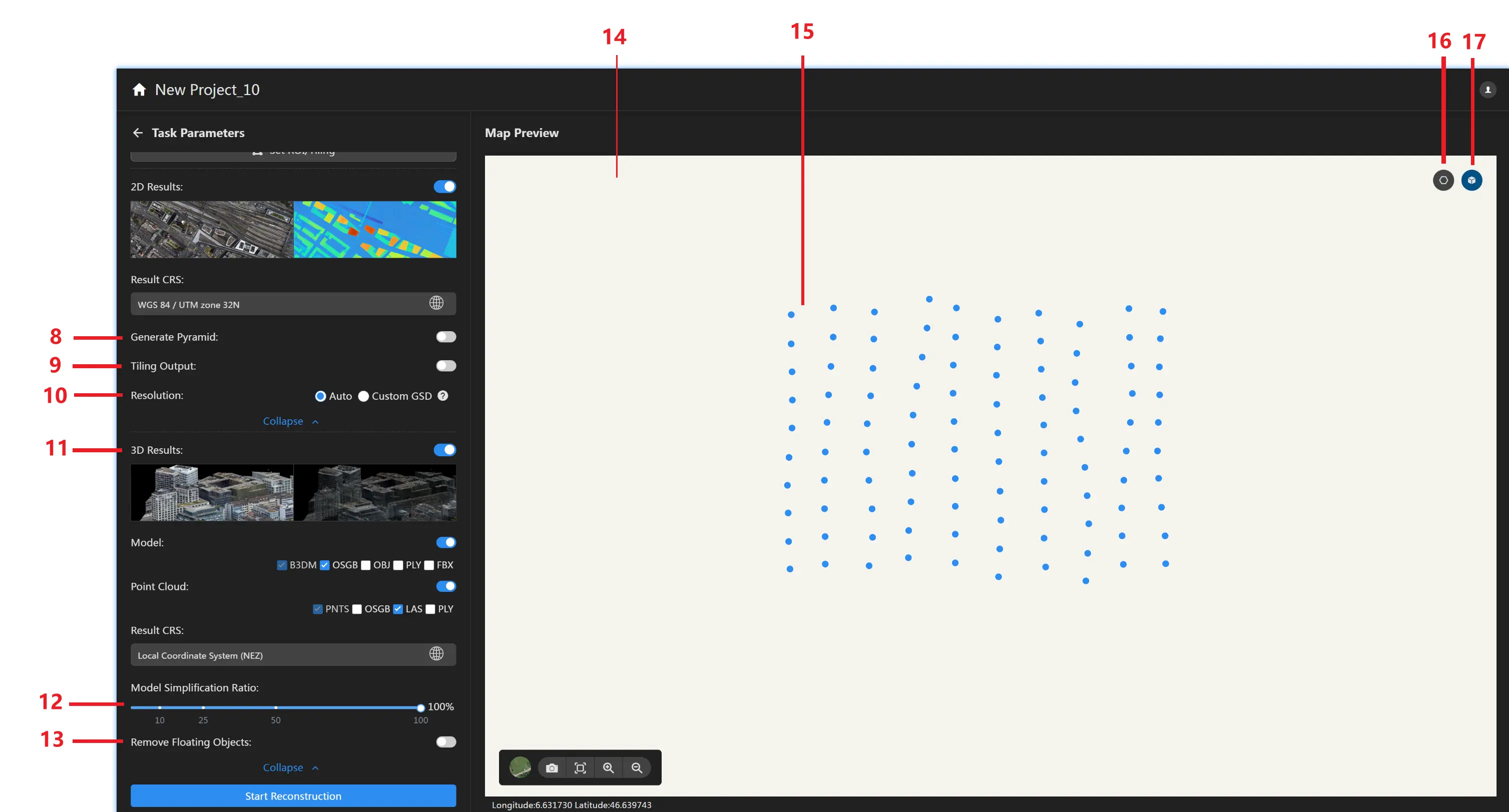
Generate Pyramids
Click More Settings in the 2D output control panel to set the 2D output format in more detail. Click the Generate Pyramids button and keep it on . After reconstruction, the orthophoto image (including tiled orthophoto images) output will include pyramid files.
Tiled Output
Click the Tiled Output button and keep it on . After reconstruction, the 2D output folder will include tiled orthophoto images. Supports setting the maximum edge length of tiled images (in pixels), with a default maximum edge length of 5000 pixels.
2D Output Resolution Setting
The 2D output resolution is automatically calculated by default based on factors such as reconstruction accuracy and photo GSD. You can also customize the GSD. The actual GSD is limited by the photo GSD. When the set resolution is too high, the number of pixels and effective resolution will not increase.
3D Output Control Panel
Click the 3D reconstruction control button and keep it on . 3D outputs (including 3D point clouds in LAS, OSGB formats and 3D models in OSGB, OBJ, PLY, 3Dtile formats) can be generated during project reconstruction.
Click the output coordinate system button to enter the coordinate system selection page. You can set the 3D output coordinate system, including geographic coordinate systems, geocentric coordinate systems, projected coordinate systems, and local coordinate systems.
The coordinate system selection page allows choosing an elevation system. Currently supports geodetic height, 1985 National Vertical Datum, and custom elevation systems. Custom elevation systems are added by importing TIF format geoid undulation files.
Model Simplification Rate
Simplify the mesh model according to the set model simplification rate. The default simplification rate is 100% to generate a complete model.
Delete Floating Objects
When enabled, unconnected floating objects around the model will be deleted.
Map Display Panel
Displays image GPS arrangement or reconstruction results.
The lower left contains the following toolset:
: Switch basemap. Click to switch the basemap to satellite map or standard map mode.
: Map snapshot. Click to take a screenshot.
: Map reset. Click to reset the map to the image GPS position.
: Zoom in map. Click to smoothly zoom in on the map.
: Zoom out map. Click to smoothly zoom out of the map.
Camera Position
After adding photos with camera positions or importing POS information after adding photos, the camera positions will be displayed on the map.
Photo Deletion
Click the area delete button in the upper right corner of the map display panel to delete photos inside or outside the drawn area.
Region of Interest
Click the region of interest display button in the upper right corner of the map display panel to select/deselect the display of the object reconstruction area.
 . 2D outputs (digital orthophoto images and digital surface models in GeoTiff format) can be generated during project reconstruction. Currently, generating orthophoto images without POS or ground control point constraints is not supported.
Click the output coordinate system button
. 2D outputs (digital orthophoto images and digital surface models in GeoTiff format) can be generated during project reconstruction. Currently, generating orthophoto images without POS or ground control point constraints is not supported.
Click the output coordinate system button  to enter the coordinate system selection page. You can set the 2D output coordinate system, including geographic coordinate systems, geocentric coordinate systems, projected coordinate systems, and local coordinate systems.
The coordinate system selection page allows choosing an elevation system. Currently supports geodetic height, 1985 National Vertical Datum, and custom elevation systems. Custom elevation systems are added by importing TIF format geoid undulation files.
to enter the coordinate system selection page. You can set the 2D output coordinate system, including geographic coordinate systems, geocentric coordinate systems, projected coordinate systems, and local coordinate systems.
The coordinate system selection page allows choosing an elevation system. Currently supports geodetic height, 1985 National Vertical Datum, and custom elevation systems. Custom elevation systems are added by importing TIF format geoid undulation files. : Switch basemap. Click to switch the basemap to satellite map or standard map mode.
 : Map snapshot. Click to take a screenshot.
 : Map reset. Click to reset the map to the image GPS position.
 : Zoom in map. Click to smoothly zoom in on the map.
 : Zoom out map. Click to smoothly zoom out of the map.
 in the upper right corner of the map display panel to delete photos inside or outside the drawn area.
 in the upper right corner of the map display panel to select/deselect the display of the object reconstruction area.